
Home | Products | About Us | News | Contact Us | Service Return Form | Obsolete Documents | Shop Online
USING HUMIDITY SENSORS WITH SIGNAL CONDITIONING
There are many types of humidity sensors, but few incorporate electronic signal processing. Two widely used units, the Honeywell HIH-4000-01 (Ohmic # HC-610) hybrid capacitive sensor and Ohmic's model SC-500 resistive sensor with signal conditioner, are sensors with integrated signal conditioners. They produce a linear DC voltage output vs. %RH making them easier to work with. Fig. 1 below shows these two units, characteristics and output equations. There are many applications for these integrated sensors in data acquisition, monitors, RH display and controllers.
Additional significant long-term factors are the costs associated with sensor replacement, field and in-house calibrations, and the complexity and reliability of the signal conditioning and data acquisition (DA) circuitry. For all these considerations to make sense, the prospective user needs an understanding of the most widely used types of humidity sensors and the general trend of their expected performance. (Definitions of absolute humidity, dew point and relative humidity are provided in the sidebar below, "Humidity Basics").

Figure 1
SELECTING YOUR HUMIDITY SENSOR
The choice of selecting a humidity sensor with signal processing depends upon environmental and cost considerations. The HC-610 provides a wide 5 to 95% RH range with a calibrated accuracy of ± 2%. The interchangeability is ± 5% from 0 to 60% RH and typically ± 8% above 60% RH. It offers good tolerance to many low percentage corrosive vapors. Maximum operating temperature is +185°F. The sensor may be light sensitive, therefore, shielding from intense light is recommended. OEM pricing as low as $13.00. Another choice, Ohmic's Model SC-500 is a resistive sensor and has an RH range of 25 to 90% with a calibrated ± 2% accuracy. It has an interchangeability of ± 4%, includes temperature compensation. The operating temperature is – 4 to +140°F. The SC-500 is a cost effective solution if the wider RH range is not required. OEM pricing under $4.50 each. Both capacitive and resistive sensors use a +5V regulated power source. Sensor selection should be made after evaluating all manufacturers’ specifications. The following outlines some applications.
HUMIDITY DISPLAY CIRCUIT
There are many ways to display the VDC Out vs. RH Data. The simplest is to connect a digital multimeter (DMM) and +5VDC regulated power supply to the sensor. Read the VDC out, then obtain the RH value from the chart or equation. The slope of the sensors’ output equation (VDC out per 1 % RH change) is 29 mV/%RH (off-set 0.78 VDC) for the HC-610 and , 22.5 mV/%RH (off-set 0.872 VDC) for the Model SC-500. Some DMM’s have a relative mode button, allowing for the zeroing of the off-set. The DMM should have a nominal 10 megohms input impedance. For a direct reading of RH, the circuit diagram in Fig. 2 can be used. The LCD display (Ohmic # 8055) is available from OHMIC INSTRUMENTS CO.

Figure 2
HUMIDITY CONTROL CIRCUIT
The humidity controller circuit diagram in Fig. 3 accepts capacitive or resistive sensor transmitters. The input signal is filtered and attenuated for improved dynamic range and is applied to the non-inverting input of an op-amp configured as a comparator. Its switch point is selectable by the potentiometer with resistance values as indicated over the full dynamic range of the signal conditioner. The set point selection is made by applying a DC voltage to the signal input with selected value from the VDC vs. % RH curves in Fig. 1, or calculated from the given equations. Once the set point is exceeded, the output of the op-amp turns on the MOSFET to activate the 5V relay.
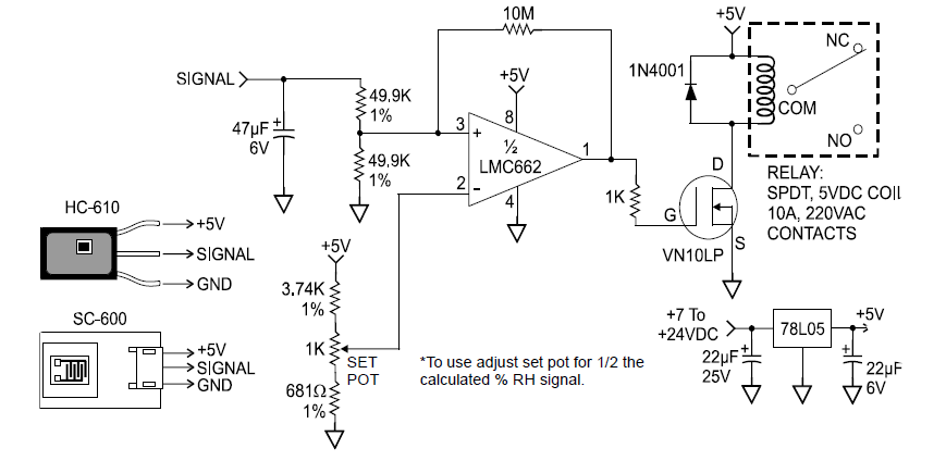
Figure 3
The sensor, signal conditioner and circuits above require a +5 VDC regulated power. You may use a “7805” to regulate the power as shown or a +5 VDC regulated power supply.